


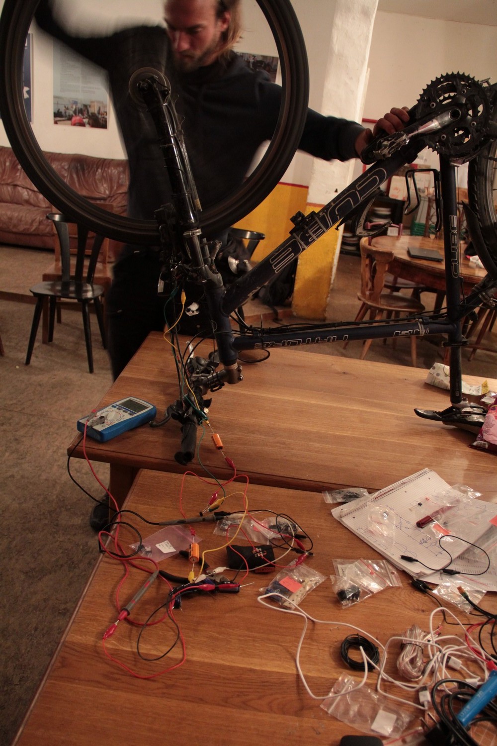
On the Spring Meeting, we did some experiments with different types of dynamo-powered USB ports:
- Once with a high-dropout DC-DC convertor, once with a low-dropout DC-DC convertor, once with a Zener diode, once with a step-down convertor (an old one, I don’t know which model it is, it cost around 10 €)
- Once with a double 3300 µF capacitor for boost (as described here), once without
- Once with a silicon rectifier, once with one made of Schottky diodes
We connected these regulators to a Shimano DH-3N30 hub dynamo, and connected a 10 Ω resistor that should simulate the charging device (500 mA at 5 V, like the maximum by the USB specification). Then we measured the wattage at the resistor at approximately constant speed of about 27 km/h. This is not at all done under scientific conditions, it is just an approximate test.
These are our results:
| Boost capacitor | Rectifier | Voltage regulator | Output | Price | Problems |
|---|---|---|---|---|---|
| None | Silicon rectifier | High-dropout DC-DC converter | 1.68 W (4.1 V × 0.41 A) | 1.08 € | Very low efficiency |
| 2×3300 µF | 1.7 W (4.25 V × 0.4 A) | 3.69 € | |||
| None | Silicon rectifier | Low-dropout DC-DC converter | 1.89 W (4.3 V × 0.44 A) | 1.37 € | Maximum input voltage 26 V, will burn from over-voltage at high speeds with no load |
| 2×3300 µF | 2.07 W (4.5 V × 0.46 A) | 3.98 € | |||
| None | Silicon rectifier | Zener diode | 2.07 W (4.5 V × 0.46 A) | 1.13 € | Burns excessive energy, will burn from over-heating at high speeds with no load |
| 2×3300 µF | 2.23 W (4.65 V × 0.48 A) | 3.74 € | |||
| None | Silicon rectifier | Step-down convertor | 1.96 W (4.35 V × 0.45 A) | 4–11 € | Expensive |
| 2×3300 µF | 2.09 W (4.55 V × 0.46 A) | 6–13 € | |||
| None | Schottky rectifier | Zener diode | 2.15 W (4.58 V × 0.47 W) | 1.16 € | Efficient Schottky diodes cannot handle high voltages |
| 2×3300 µF | 2.34 W (4.77 V × 0.49 W) | 3.77 € |
Note that for actually building the device, there will be additional costs for cables, a switch, connectors, a USB port etc. of minimum around 1.50 €.
- The Zener diode performed the best, and is also relatively cheap. The disadvantage is that it just burns the energy that you don’t use, so particularly when you have no devices connected it gets very hot (and some people believe that you can notice it slowing you down). It would probably burn without a heat sink.
- The boost capacitor definitely improved the result, and according to the manual where we got the idea it particularly improves the result at slow speeds. The disadvantages are that they cost some money, and they take quite some space compared to the rest of the device.
- The Schottky diodes performed better than the silicon rectifier. However, during our tests, several of them burned, so we couldn’t test the Schottky diodes with the other types of voltage regulators.The Schottky diodes that we bought have a maximum reverse voltage of 30 V, but measuring the dynamo without load produced at least 35 V. There are some cheap Schottky diodes that can withstand a much higher voltage, but with them the voltage drop is comparable to normal silicon diodes.
We want to do a workshop in the beginning of the Biketour where we all build dynamo-powered USB ports together. We are not sure yet about which combination of items to use, as the Zener diode is likely to burn when not used properly, the step-down converters are expensive, and the low-dropout voltage regulators are only specified for an input voltage of maximum 26 V, which the dynamo exceeds when there is no load according to our measurements.
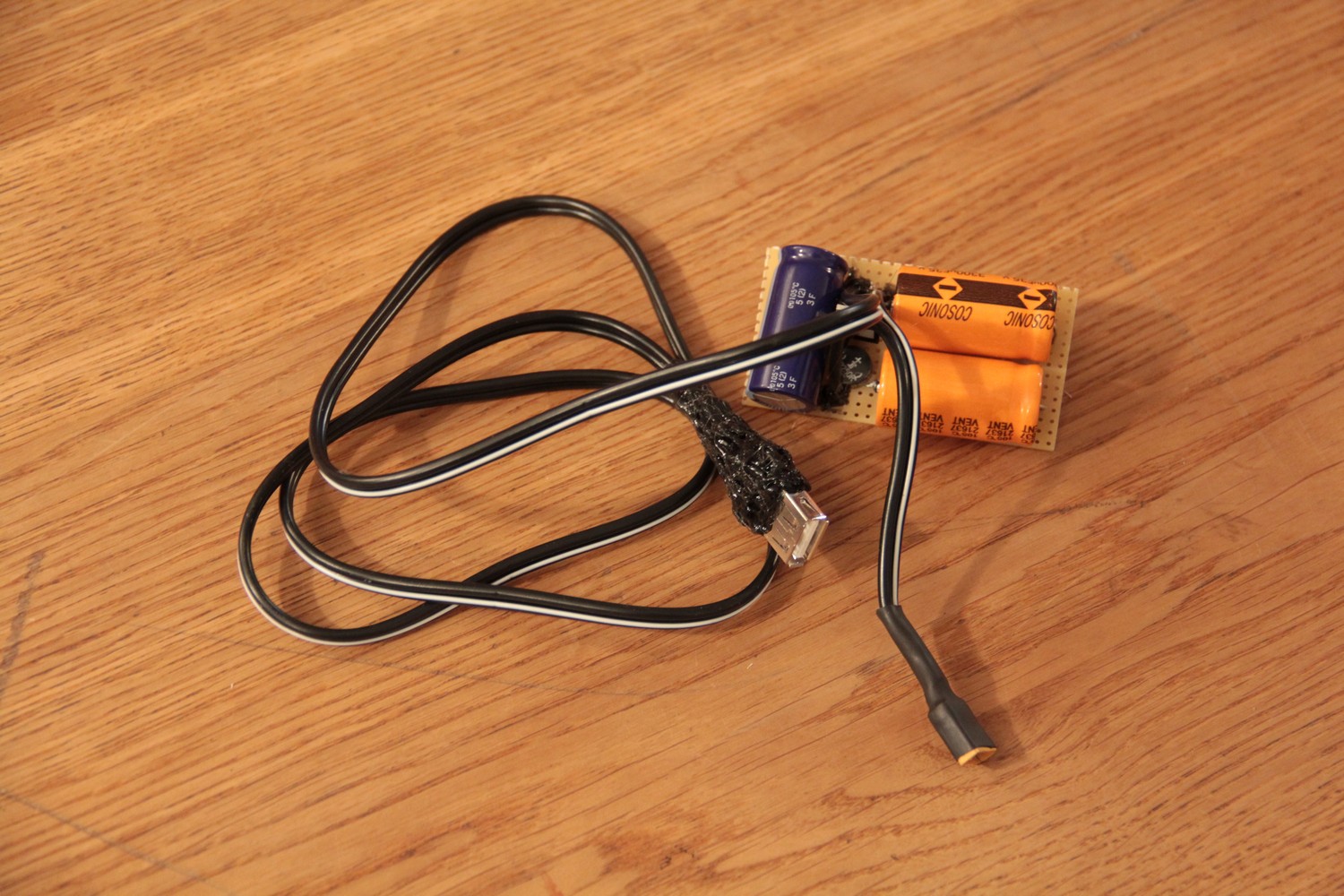
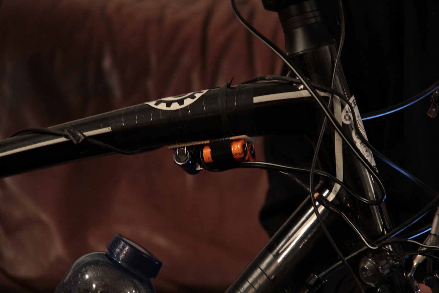
In the end we built one device with a silicon rectifier and a low-dropout voltage regulator and installed it on a bike. If it doesn’t burn in practice, this might be the best option.
There are two more options that we discovered after our experiment, which we still need to try out:
- Using MOSFETs for rectifying. They have practically no voltage drop. The problem is that they cannot handle high voltage, so we would need a Zener diode for over-voltage protection (which brings back the problem of overheating), and they conduct electricity in both directions, so if we add a buffer capacitor, the electricity from it would go back into the dynamo, so some diodes are needed, intoducing a voltage drop again (but it would be only one diode, not two). What’s not so nice about this solution is that it is more difficult to understand, so maybe not suitable for a workshop.
- Regulating the voltage before the rectifier using two Zener diodes in series in opposite polarisation. This is a really interesting idea, as it removes the problem of over-voltage on the rectifier (so we could use efficient Schottky diodes), and the Zener diodes could be in a different place than the rest, attached somewhere to the cable, in a well-ventilated place, maybe using the bike frame as a heat sink. The voltage of the Zener diodes probably has to be a bit higher than 5 V to make up for the voltage drop on the rectifier.
When researching about topics like these online, there is a huge amount of contradicting information and opinions. We are not professionals – if you think we have made a mistake, please let us know in the comments!