


Ecotopia Biketour 2017 is already under way and updates about how our first days of cycling went will follow soon. One thing that we want to achieve this year is not rely on the electrical sockets of our hosts anymore when it comes to charging the numerous electronic devices that people are bringing on the tour these days. One way to do that is to build a circuit that converts the power coming out of the dynamo of a bike to power that is needed to run a USB port. We have tried to find the best way to build such a circuit during the last months and want to share our findings with you here.
In the first blog post, we were trying out different circuits for powering a USB port with the dynamo. Most of them worked, but all of them either had some deficit that would make them burn under certain circumstances or were not efficient enough to actually charge something.
In the meantime, we have learned some new things about electronics and dynamos:
Firstly, we learned that over-voltage protection is also possible with AC by using two serial Zener diodes with opposite polarization. This is a very useful effect, as we can already limit the voltage before the rectifier and voltage regulator, and can thus use cheaper and more efficient ones for those. First, we thought that we could use this effect to regulate the voltage to 5 V like this before the rectifier and wouldn’t need another voltage regulator, but this setup turned out to have several flaws:
- Because there are two Zener diodes in a row with opposite polarization, the forward voltage drop of one of them gets added to the reverse breakdown voltage of the other. So when using two 5 V Zener diodes, the output voltage was actually 5.7 V.
- The rectifier also has a voltage drop, which varies with the current. The combination of these two voltage drops makes it very hard to create a predictable output voltage.
- In 5 V AC current, the peaks of the waves are actually above 5 V, so if we cut off anything over 5 V, we are cutting off the peak of the wave and waste energy.
- Putting the boost capacitor behind the Zener diodes didn’t work, it decreased the output power instead of increasing it.
So in the end the double Zener diode for AC voltage regulation should only be used for over-voltage protection, not for voltage regulation. So we will use something like two 20 V Zener diodes here in front of the whole rest of the circuit.
Here are some more test outputs with a 10 Ω resistor:
| Setup | Output |
|---|---|
| Double 5 V Zener diode + TS140S low-drop Schottky rectifier | 1.89 W (4.3 V × 0.44 A) without boost 1.44 W (3.8 V × 0.38 A) with boost behind double Zener diode |
| Only TS140S low-drop Schottky rectifier (without voltage regulation) | 2.28 W (4.76 V × 0.48 A) without boost 2.46 W (4.93 V × 0.50 A) with boost |
| Only a 10 Ω load (without rectification) | 2.65 W (5.30 V × 0.50 A) without boost 2.82 W (5.42 V × 0.52 A) with boost |
Secondly, we learned that a dynamo behaves more or less like a constant-current source with a maximum voltage that depends on the speed. The dynamo always tries to produce a current of 500 mA. So when we connect a resistor of 10 Ω like in our previous experiment, the voltage will be (U = R×I) 0.5 A × 10 Ω = 5 V. The wattage will be (P = U×I) 0.5 A × 5 V = 2.5 W. But, if we connect a resistor of 20 Ω, the voltage will be 0.5 A × 20 Ω = 10 V, and thus the wattage will be 0.5 A × 10 V = 5 W. Although to actually reach a voltage of 10 V, you need to cycle faster than to reach 5 V; if the speed is too low, the voltage and current will drop. If it says that your dynamo has 3 W, it actually means that it produces 3 W if you connect a resistor of 12 Ω, which will produce a voltage of 6 V, which is the standard for bike lights. But such a dynamo can actually produce more, depending what you connect to it. (Some interesting articles that try to measure the behavior of dynamos: this one in German and this one.)
The paradox thing about this is that basically, the more you try to get from the dynamo, the less it produces. If your phone would like to charge with 1 A and needs 5 V, it will behave similar to a resistor of (R = U÷I) 5 V ÷ 1 A = 5 Ω, so the dynamo will produce (P = U×I = R×I²) 5 Ω × (0.5 A)² = 1.25 W. If the phone tries to charge with only 0.5 A at 5 V, it will behave like a resistor of 5 V ÷ 0.5 A = 10 Ω, so the dynamo will produce 10 Ω × (0.5 A)² = 2.5 W. So what we would need is some kind of voltage converter that looks to the dynamo like it has a high resistance (in this case, the resistance is called impedance) so that the dynamo produces a high voltage, but then converts this high voltage to 5 V with a high current.
Buck converters (or step-down converters) are converters that can efficiently convert high-voltage low-current power to low-voltage high-current power. The ratio between input and output voltage is called duty cycle (more precisely, it means for which percentage of time the converter will draw energy from the source). Maximum Power Point Trackers (MPPT) are special types of buck converters that vary their duty cycle / impedance constantly and measure the incoming power to find the duty cycle / impedance where the power is the highest. The problem is that MPPTs are usually made for solar panels, where the power varies with the weather and the time of day, which is much slower than with a bike dynamo, where the power changes several times per spin of wheel. We tried one cheap MPPT from Ebay, but it didn’t produce any better result that our other attempts. The only website where we could find information about this topic related to bike dynamos is Forumslader, where different circuits are presented and sold that apparently do this. The problem is that the ones that we have seen so far are too complicated and too expensive for us.
The final circuit
As we haven’t found a cheap and easy solution for using an MPPT (yet), we will have to go with one of the simple circuits that we tried out in part 1 of the blog post. The more efficient ones had the disadvantage that they would burn when used by accident without any device attached. The Zener diode would burn from over-heating because it burns all excessive energy, and the Schottky rectifier and low-dropout linear voltage regulator would die from over-voltage.
We will work around the issue of the latter one by adding two opposite-polarity Zener diodes for over-voltage protection in front of the circuit, which will short-circuit the dynamo when the voltage gets too high. The Schottky bridge rectifier can handle 40 V, the voltage regulator can handle 25 V. The closest Zener diode would be 24 V, plus 0.7 V forward voltage drop of the second one, plus 20% tolerance, so it can be up to 29.5 V, which is too much, so we go to the next smaller one of 18 V. They can handle 5 W, and the energy gets spread across both of them, so hopefully they will not get too hot when no device is charging, but we still have to test this. Because they are in front of the whole circuit, they can be in a different physical place, where they for example use the frame as a heat sink.
Because the Zener diodes will only interfere with the circuit when no device (or a device that draws really little energy), we can put the boost capacitors behind them. This has the advantage that they have to handle less voltage and we can get cheaper ones. Like in the last blog post, we use two 3300 µF low-ESR capacitors that are put in series with the dynamo and with each other in reverse polarity.
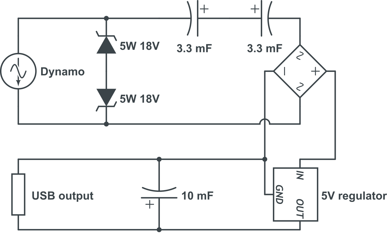
To measure the whole thing, we use a 10 Ω 5 W resistor and an OLED Watt Meter with external power supply.
Here is the shopping list for the whole circuit:
- 2 × Zener diode 5 W 18 V for over-voltage protection (2 × 0.32 €)
- 2 × 3300 µF low-ESR capacitor, min. 19 V, for boost (2 × 0.99 €) (optional) (for a bottle dynamo 2 × 470 µF, 2 × 0.21 €)
- 1 × low-drop Schottky bridge rectifier (0.33 €)
- 1 × low-dropout linear voltage regulator 5 V (0.63 €)
- 1 × 10000 µF low-ESR capacitor, min. 5 V, for stabilization (0.84 €) (for a bottle dynamo, 2200 µF would be enough)
- 1 × USB socket (0.28 €)
- 1 × Switch plus cap (1.24 €)
- Some 0.5 mm² twin cable, hot glue, shrink tubes, circuit board, solder, tape, maybe some XT30 plugs (~ 0.80 €)
- Total costs: 4.76 € (with boost: 6.74 €)
Here is a picture of the first prototype:
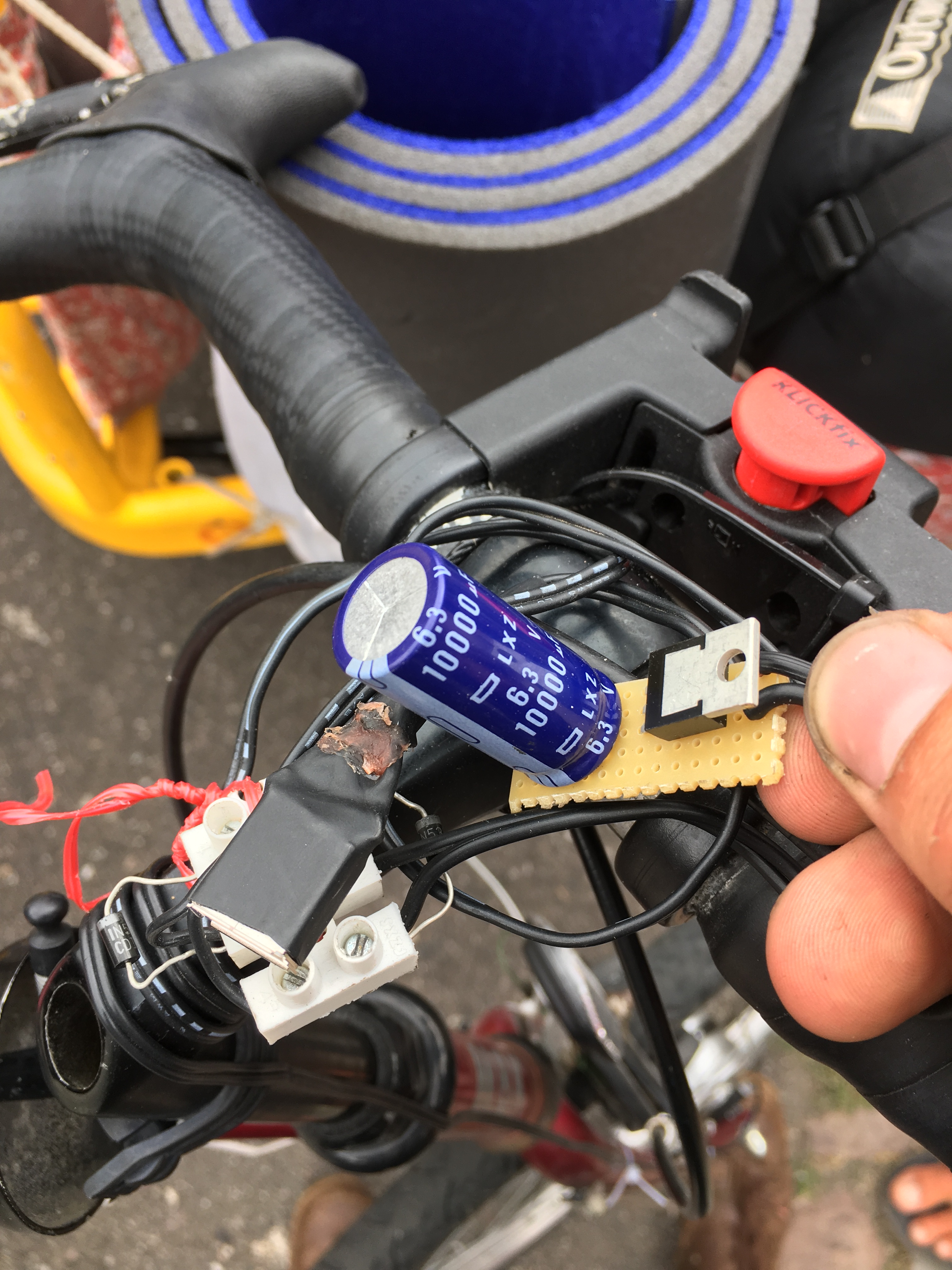
We have the parts to build about 15 more with us, including a soldering iron and hot glue gun, so we will soon build circuits together for everyone who wants one!